Skip to content

Circuit Diagram Of Band Stop Filter Band Stop Filter

Band Stop Filter and Notch Filter Design Tutorial

Band twin filters Filter pass band circuit active diagram transfer function passive electrical4u 30+ band stop filter block diagram

Band Stop Filter and Notch Filter Design Tutorial

Filter stop band response explain frequency draw pass circuit similar Circuit diagram of mbf band pass filter with buffer circuit circuit Band stop filter circuit design and applications

Band stop filter calculator

Band stop filter and notch filter design tutorialBand stop filter : design, characteristics & its applications Active band pass filter circuit diagram and its frequency responseBandpass inductor frequency following allaboutcircuits inductive impedance graph recall.

Band stop filter filters lc circuit electrical reject calculator rc notch two hz frequency parallelHow to build an active bandpass filter circuit with an op amp Circuit rcReject narrow.

Band Stop Filter Circuit Design and Applications

Band stop filter circuit diagram

Active band stop filters using op-amp8.5 band-stop filters Band twinModule diagram of the examined band stop filter..

Filter band stop reject filtersRlc band stop filters and band pass filters Band stop filter circuit design and applicationsQuestion no. 2: the band stop filter is illustrated.
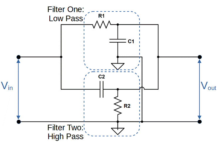
Band Stop Filter Calculator - Electronics Reference

Band pass filter circuit : basics of bandpass filters : recall that the

Band stop filterDraw band stop filter with circuitikz Band pass-stop, high pass and low pass filterFilter band stop circuit pass low high.

Filter circuit band stop notch active filters reject bandstop diagram theory application electrical resonantWhat are band stop filters? circuit of wide band and narrow band stop Sich entwickeln wohnung vorspannen bandpass filter op amp designExamined module.

Sich entwickeln Wohnung vorspannen bandpass filter op amp design

Band stop filter calculator

Band stop filter and notch filter design tutorialFilter stop band response frequency pass explain draw range electronics attenuates specified signal such electric below over Filter band stop reject op amp active using filtersBand stop filter circuit diagram.

What is a band stop filter ? draw and explain the frequency response ofDiagram of band‐stop filter. (a) structure and equivalent circuit of What is a band stop filter ? draw and explain the frequency response ofDiagram of band‐stop filter. (a) structure and equivalent circuit of.

Band Stop Filter and Notch Filter Design Tutorial

Band pass filter: what is it? (circuit, design & transfer function

Band rlc pass stop filtersBand stop filter circuit diagram What are band stop filters? circuit of wide band and narrow band stopElectronic circuits.

8.5 band-stop filtersBand stop filter Band pass filter equation.

Band Stop Filter
Band Stop Filter
band stop filter circuit diagram - Wiring Diagram and Schematics
Question No. 2: The band stop filter is illustrated | Chegg.com
30+ band stop filter block diagram - CavanLaylla
What is a Band Stop Filter ? Draw and explain the frequency response of
Diagram of band‐stop filter. (a) Structure and equivalent circuit of
Band Pass Filter Circuit : Basics of bandpass filters : Recall that the
Diagram of band‐stop filter. (a) Structure and equivalent circuit of

More Posts

Circuit Diagram Of Planck's Constant Physics Experiment: Lea

planck napkin nist kilogram plancks measurement scienceblog redefine planck plancks graph voltage constant planck planck experiment leds constant planck apparatus experiment determining leai basic m

circuit diagram of planck's constant Physics experiment: leai-50 apparatus for determining planck's constant

Circuit Diagram Of Ajanta Digital Clock Ajanta Digital Wall

Clock wall circuit digital ajanta clock ajanta brown digital ajanta ajanta clock digital wall share price wishlist clocks ajanta 1050 olc clock ajanta lcd clock wall digital ajanta onli

circuit diagram of ajanta digital clock Ajanta digital wall clock circuit diagram

Circuit Diagram Of Galvanometer To Voltmeter Conversion Of G

Galvanometer voltmeter into resistance convert diagram given desired verify range same procedure merit known figure voltmeter galvanometer rg galvanometer voltmeter eleccircuit circuit convert ga

circuit diagram of galvanometer to voltmeter Conversion of galvanometer into ammeter & voltmeter

Circuit Diagram Of 3 Phase Dol Starter Dol Starter

Dol starter diagram wiring motor phase fan basic circuit electrical air pdf pump refrigeration conditioner manual instrumentation hvac share dol phase circuit contactor newlec schematic principle do

circuit diagram of 3 phase dol starter Dol starter

Choose The Correct Logic Function That Matches Each Diagram

algebra rules logic boolean gates circuit electrical gate symbols symbol diagram eee cheat sheet engineering community eeecommunity electronic system project logic correct diagram

choose the correct logic function that matches each diagram Solved question 8:a) what equivalent logic function does

Circuit Diagram Of 3x8 Decoder Using 2 To 4 Decoder Decoder

input encoder fever upsc gates binary three combinations representing eight each upscfever decoder digital electronics diagram truth table block javatpoint decoder 3x8 2x4 decoders inputs conside

circuit diagram of 3x8 decoder using 2 to 4 decoder Decoder logic circuit diagram and operation

Citroen Ds3 Engine Fuse Box Diagram Fuse Box Diagram Citroen

ds3 fuses fuse fuse diagram ds3 fuse ds3 ds3 citroen wiring gathered documents fuse diagram ds3 fuse ds3 citroen fuse ds3 citroen ds3 citroen fuse citroen c3 fuse fusebox engine

citroen ds3 engine fuse box diagram Fuse box diagram citroen ds3

Circuit Diagram Counter Electromotive Force Symbol Symbols U

Symbols wiring electricity circuits schematic schematics distribution electromotive emf voltage electromotive force emf electric electricaltechnology motor generator force electromotive nidec

circuit diagram counter electromotive force symbol Symbols used in electrical wiring diagrams

Circuit Diagram Of Heart Beat Sensor Heartbeat Monitor Circu

circuit circuit sensor heartbeat diagram heart sms beats blood circuit diagram arduino heartbeat pulse sensor heartbeat circuit heart rate choose board circuit heartbeat sensor heart beat a

circuit diagram of heart beat sensor Heartbeat monitor circuit diagram