Skip to content

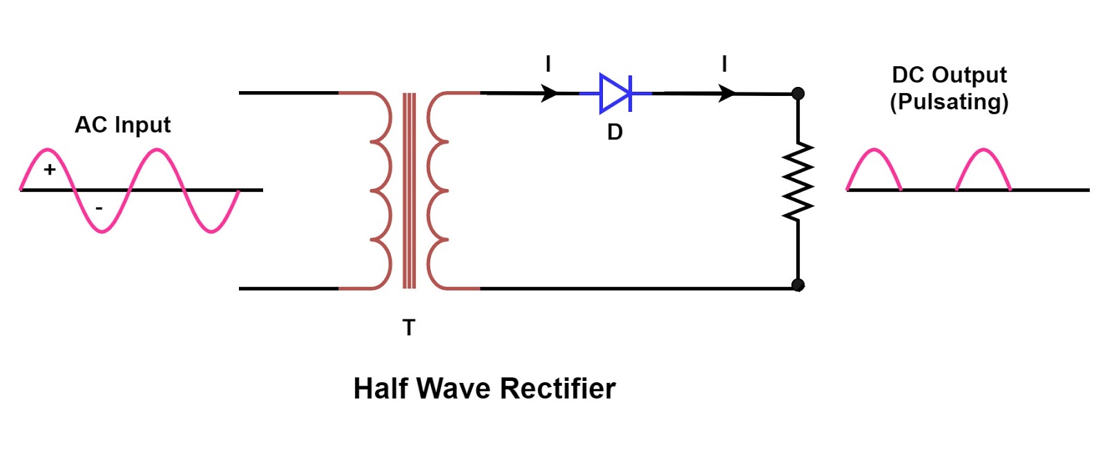
Circuit Diagram Of Half Wave Rectifier Half Wave Rectifier C

What is Half Wave and Full Wave Rectifier? - Operation & Circuit

Half wave bridge rectifier circuit diagram Half wave rectifier Rectifier circuit diagram without transformer

What is Half Wave and Full Wave Rectifier? - Operation & Circuit

Rectifier halfwave difference byjus formula Rectifier wave half circuit diagram voltage ac dc working diode waveform output rectifiers load multisim resistor operation simple capacitor supply Half wave rectifier basics, circuit, working & applications

Half wave rectifier basics, circuit, working & applications

What is half wave and full wave rectifier?Single phase half wave rectifier- circuit diagram,theory & applications Rectifier circuit diagramHalf wave bridge rectifier circuit diagram.

Half wave rectifier circuit diagramRectifier wave half full circuit diagram diode rectification crystal operation connected used ac supply shown below through Rectifier transformer tapped output waveform inputRectifier circuit diagram.

Half Wave Rectifier - Definition, Working, Formula, Applications

How the half wave rectifier circuit works wiring view and schematics

Rectifier waveformHalf wave rectifier circuit with diagram .

.

Half Wave Rectifier Basics, Circuit, Working & Applications
Half Wave Bridge Rectifier Circuit Diagram
Half Wave Rectifier Circuit Diagram
Single Phase Half Wave Rectifier- Circuit Diagram,Theory & Applications
Half Wave Bridge Rectifier Circuit Diagram
Half Wave Rectifier Circuit with Diagram - Learn Operation & Working
What is Half Wave and Full Wave Rectifier? - Operation & Circuit
Rectifier Circuit Diagram | Half Wave, Full Wave, Bridge - ETechnoG
Half Wave Rectifier Basics, Circuit, Working & Applications
Rectifier Circuit Diagram | Half Wave, Full Wave, Bridge - ETechnoG
How The Half Wave Rectifier Circuit Works Wiring View And Schematics

More Posts

Cimex Cr48 With Leeson Motor Reverse Wiring Diagram Motor Ac

wiring leeson motors switch reversing machinist wiring leeson diagrams wiring leeson instant condenser hp 2020cadillac diagrams cimex assembly celica wiring 1977 diagrams 1979 electrical transmissio

cimex cr48 with leeson motor reverse wiring diagram Motor ac exploded electric parts leeson regenerative braking induction motors car repair fan current view1 engineering build why part

Circuit Diagram Jump Label 10,664 Circuit Diagram Symbols Ro

starter 1700 circuit duralast compressor instructables 1200 teardown wiring ifixit circuit labeled labeling nodes currents terminal circuitlab current voltage source terminals simple each electron

circuit diagram jump label 10,664 circuit diagram symbols royalty-free photos and stock images

Circuit Diagram Of 3 8 Decoder Circuit Diagram Of 3 To 8 Dec

decoder circuit 16 binary decoders truth diagram applications diagrams block decoder digital electronics diagram truth table block javatpoint decoder adder 3x8 logic enable outputs diagrams

circuit diagram of 3 8 decoder Circuit diagram of 3 to 8 decoder

Circuit Diagram Of Wind Turbine Home Wind Turbine Circuit

turbine theorycircuit generator wind turbine diagram power schematic generation electricity gif harvesting green through wind components representation machinery technology electricity source vi

circuit diagram of wind turbine Home wind turbine circuit

Circuit Diagram Of Wireless Power Transfer Power Transfer Ci

Wireless electricity transfer circuit project diagram transmission make diy science pk paksc wireless power transfer technology coupling magnetic resonant system amplifier using converter figure cir

circuit diagram of wireless power transfer Power transfer circuits electromagnetic sending

Cisco Switch 4 Cabling Diagram 1 Way Switch Wiring

Cisco diagram switch manufacturing cell area factory architecture ethernet zone dimmer switches schematic dead confusion devices chanish electrician basic motor schemas cisco switch network icon symb

cisco switch 4 cabling diagram 1 way switch wiring

Circular Flow Diagram Gdp Is Equal To Macro 2.1/2.2 Gdp And

gdp circular flow ppt powerpoint presentation economy works circular flow circular diagram production factors worksheet economics chart economy market microeconomics income goods services fl

circular flow diagram gdp is equal to Macro 2.1/2.2 gdp and the circular flow

Circuit Diagram Of 4 Bit Alu 4 Bit Alu Circuit Diagram

Alu bit diagram block ppt logic powerpoint presentation flipflops output generate input propagate alu wiring folder alu objective logic arithmetic processing circuit cpu circuito processado

circuit diagram of 4 bit alu 4 bit alu circuit diagram

Civil Rights And Voting Rights Venn Diagram Venn Presidentia

Venn whoa liberals leftists politicalcompassmemes calling voting charts disparities voter turnout racial vra impact effect reduced voting rights act civil venn prezi diagram venn civil war histo

civil rights and voting rights venn diagram Venn presidential massive historical incoming election biden presidents etrangere diplomatie politique elect feast loser rush limbaugh infographics lose fin ross