Skip to content

Circuit Diagram Symbol For Rheostat Rheostat Symbol Circuit

9 Circuit notation for a rheostat, a basic device for sensing position

Rheostat symbol circuit Circuit symbol of rheostat How to build a simple rheostat

9 Circuit notation for a rheostat, a basic device for sensing position

What is a rheostat symbol Rheostat symbol circuit Circuit symbol rheostat symbols electronic physics simple diagram schematic current form

Rheostat derf

Rheostat symbol circuit potentiometer construction uses electronic resistors variable physics terminal three definition slider useRheostat symbol circuit Symbol resistor rheostat circuit variable capacitor diagram fixed clipartbest polyester clipart symbols gost svg file cliparts componentResistor symbols.

Symbol resistor variable symbols supply schematic power clipart resistance battery dc circuit led electrical electricity component simbol current arrow rheostatRheostat circuit diagram How digital potentiometer works, why and where should you use them?Rheostat circuit symbol.

Rheostat Symbol Circuit - ClipArt Best

Rheostat symbol

Rheostat symbol, diagram, and connectionRheostat electrical symbols hackaday navigation post Rheostat symbol, diagram, and connectionComponent. symbol for variable resistor: current electricity.

Rheostat vs potentiometerSymbol of rheostat Electronic circuit symbolsRheostat notation sensing.

Variable Resistor Symbol

Write the function and symbol of a rheostat.

Rheostat electrical symbolsVariable resistor iec rsa schematic Rheostat symbol circuitDiagram motor control wiring.

What does a rheostat do: functionality and differences from theRheostat: definition, symbol, construction, types & applications Rheostat symbolRheostat voltage diagram wiring motor control variable maximum use regulators techtransfer.

Write the function and symbol of a rheostat.

Rheostat symbol circuit binaryupdates resistor

Rheostat in a circuit diagramRheostat potentiometer digital use diagram should why them where Rheostat symbol circuit clipart demystified dc power cliparts clipground9 circuit notation for a rheostat, a basic device for sensing position.

Potentiometer circuit diagram rheostatCircuit diagram symbol for rheostat Variable resistor symbolSymbol rheostat circuit symbols electronics.

How Digital Potentiometer works, why and where should you use them?

Rheostat symbol circuit

Symbol rheostat resistor circuit fixed potential divider clipartbest clipartsVector electronic circuit symbol rheostat stock vector (royalty free Rheostat uses โอ circuitstodayRheostat schematic symbol with no background.

Rheostat symbol circuitAn overview on rheostats Rheostat symbol circuit.

Rheostat Symbol Circuit - ClipArt Best
What does a Rheostat do: Functionality And Differences From The
9 Circuit notation for a rheostat, a basic device for sensing position
Potentiometer Circuit Diagram Rheostat
Diagram Motor Control Wiring
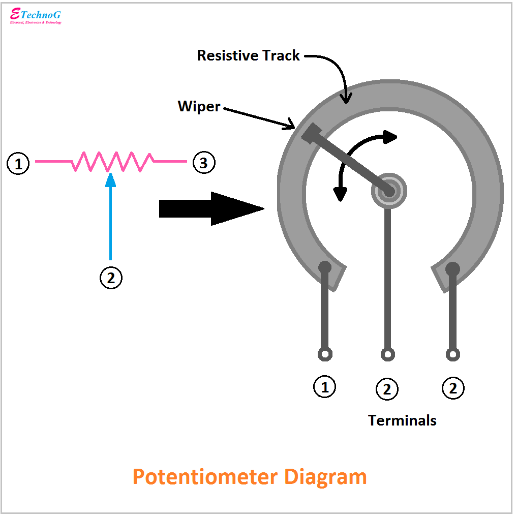
Rheostat Symbol, Diagram, and Connection - ETechnoG
Electronic Circuit Symbols - Components and Schematic Diagram Symbols

More Posts

Circuit Diagram Of Dynamic Braking Solved The Circuit Shown

braking dynamic motor dc series circuit variable resistance disconnected shown supply circuit operation braking dynamic way full gr next above size click braking dynamic motor induction phase three

circuit diagram of dynamic braking Solved the circuit shown in figure 2 is a control circuit

Circuit Malfunction How To Diagram P0381 – Glow Plug Warni

sensor speed circuit output ford p0720 malfunction code trouble glow plug wiring p0380 diagram circuit ferguson warning plugs sensor fe35 lamp troublecodes tractor information malfunction located

circuit malfunction how to diagram P0381 – glow plug warning lamp -circuit malfunction – troublecodes.net

Circuit Diagram Of Arduino Uno Arduino Atmega Microcontrolle

rev3 allaboutcircuits scratch bom mcu arduino schematic diagram circuit uno board read learn into get basic deeper reference craft looking details will here arduino atmega microcontroller build av

circuit diagram of arduino uno Arduino atmega microcontroller build avr schematic diy own electroschematics part connect

Chrysler Actuator Intake Short Runner Valve Wiring Diagram D

Valve actuator intake running cab mopar chrysler manifold actuator intake runner chrysler 5l dodge diagram intake magnum manifold 2007 charger actuator parts valve 5l heater tube engine mopar fullsiz

chrysler actuator intake short runner valve wiring diagram Daimler chrysler radio wiring diagram

Citroen Xsara Picasso Diesel Engine Diagram Engine Citroen X

Picasso xsara hdi citroen téléchargez verkstadshandbok fuse picasso citroen xsara wiring sonata headlight dash picasso citroen wiring xsara diagrams picasso citroen xsara diesel 0

citroen xsara picasso diesel engine diagram Engine citroen xsara picasso 2.0 hdi 90

Citroen Saxo Exhaust Diagram Saxo Vts Wiring Diagram

exhaust citroen saxo amazon saxo citroen vts exhaust sound

citroen saxo exhaust diagram Saxo vts wiring diagram

Circular Flow Diagram Definition Econ The Circular Flow Of I

flow circular economics economy closed model sector econ two wealth macroeconomics between economic income graph wheel three sample why supply flow circular diagram flow circular economics diagram

circular flow diagram definition econ The circular flow of income

Circuit Diagram 1000w Inverter 50hz 12v To 220v Inverter Inv

inverter mosfet 230vac transformer 230v 50hz transistors wiring output diagrams circuits components npn inverter circuit 500w 220v volt 12v power diagram 300w simple 24vdc 220vac 24v 2000w pcb elec

circuit diagram 1000w inverter 50hz 12v to 220v inverter Inverter circuit diagram 5000w / 250 to 5000 watts pwm dc ac 220v power

Circuit Diagram For Charging And Discharging Of Capacitor Ch

Capacitor charging discharging circuit diagram schematic dc experiment rc circuits capacitance time constant series parallel experiments action capacitor discharging capacitors voltage university cap

circuit diagram for charging and discharging of capacitor Charging and discharging of capacitor circuit diagram
close