Skip to content

Circuit Diagram To Convert 12v To 5v How To Convert 12v To 5

12 Volt Dc To 6 Volt Dc Converter Circuit Diagram

5v to 12v, dc to dc boost converter circuit gadgetronicx 12v to 5v converter Simple 5v to 12v step up dc-dc boost converter circuit

12 Volt Dc To 6 Volt Dc Converter Circuit Diagram

12v to 5v 230v dc ac circuit converter 5v diagram 48 volt dc 12 volt dc converter circuit diagram

3v to 12v converter circuit diagram

12v 5v converter circuit dc circuitscheme voltage source scheme5v 12v converter regulator step down using ways dc 5v to 12v converter circuit diagram » circuit diagramHow to convert 12v to 5v using transistor // 12v to 5v converter.

Lm7805 pinout5v to 12v voltage boost 5v to 12v converter circuit diagram12v to 5v converter circuit || how to make 12v to 5v converter circuit.

5v To 12v Converter Circuit Diagram

12v to 5v converter using lm7805 ic

How to convert 48v to 12v12v 5v converter resistor circuits simple circuit projects using 5v to 12v, dc to dc boost converter circuit gadgetronicx, 49% offConvertor circuit diagram.

Many ideas of 12v and 5v dual power supply circuit diagram at 3a maxConvert 9v to 5v circuit diagram Converter 12 volt to 5 volt : 5 steps (with pictures)Ac dc wiring diagram.

10+ 12V To 5V Converter Circuit | Robhosking Diagram

12 volt dc to 6 volt dc converter circuit diagram

12v to 5v converter5v to 12v step up dc-dc converter 12v to 5v converter wiring diagramConvert photo to circuit diagram.

12v to 5v converter- 4 simple circuits for projects12v dc to 5v dc converter circuit diagram 12v to 5v converter circuit diagram5v-12v conversion circuit.

3v To 12v Converter Circuit Diagram

12 to 5 volt converter circuit (for cars)

Make 12v to 5v converter circuit 5a, 12v to 5v power supply circuit12v to 5v converter circuit proteus simulation 10+ 12v to 5v converter circuitEeetricks.blogspot.com: 230v ac to 5v dc converter circuit diagram.

Make 12v to 5v converter circuit 5a, 12v to 5v power supply circuit5v 12v voltage boost circuit pcb layout .
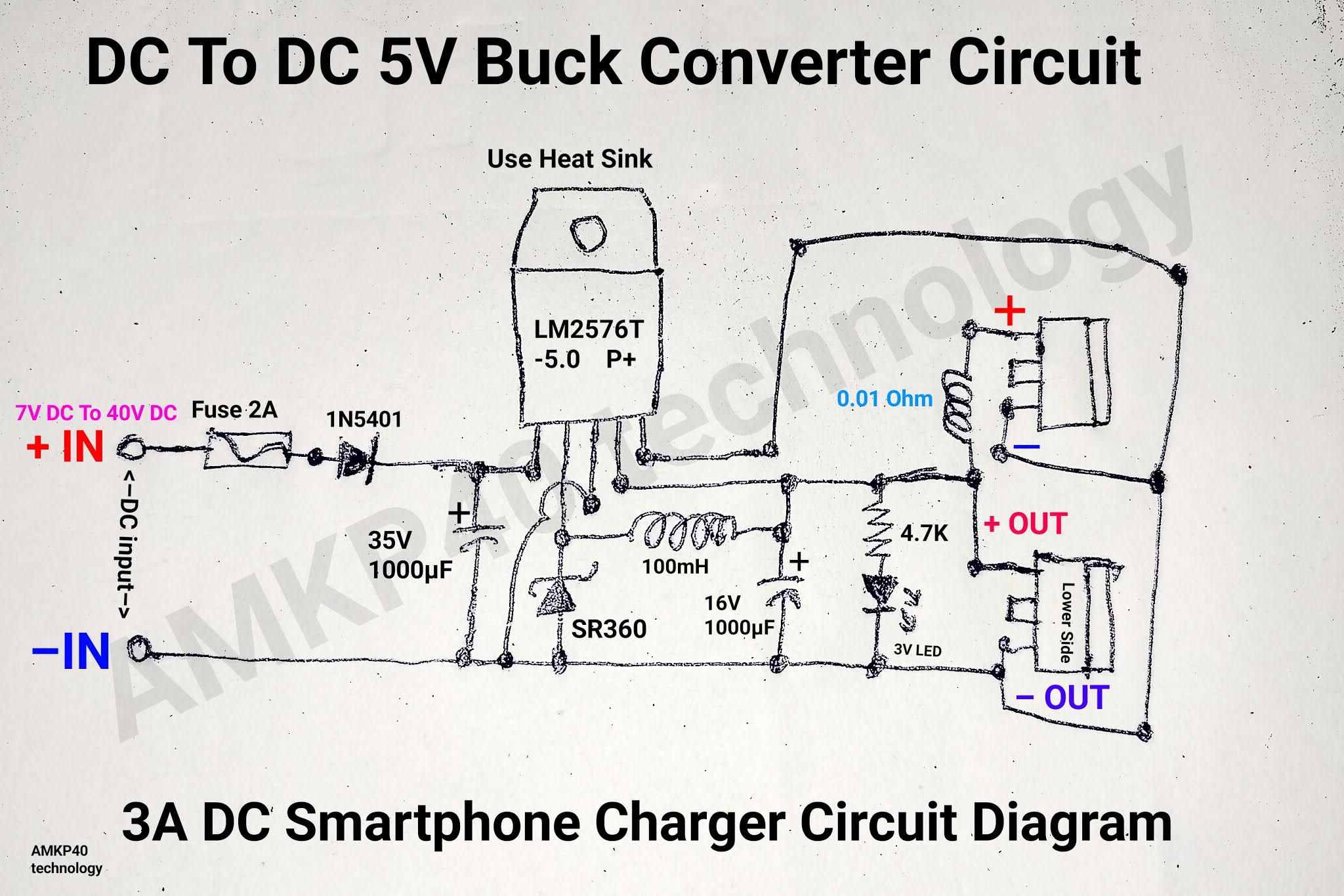
12v Dc To 5v Dc Converter Circuit Diagram
12v to 5v Converter- 4 Simple Circuits for projects - SM Tech
How to convert 12v to 5v using transistor // 12v to 5v converter
12 Volt Dc To 6 Volt Dc Converter Circuit Diagram
LM7805 Pinout
LM7805 Pinout
Convertor Circuit Diagram
12V to 5V Converter Circuit Proteus Simulation - The Engineering Knowledge
5V-12V conversion circuit | Download Scientific Diagram
Ac Dc Wiring Diagram

More Posts

Circle Diagram Of Induction Motor Is Used To Determine Circl

circle diagram induction motor line draw construction parts representing voltage rated vertical induction induction axis oy circle diagram induction motor point parts operating load full constr

circle diagram of induction motor is used to determine Circle diagram motor induction point locating load fig full

Circuit Diagram 7 Segment Display 7 Segment Display Clock Ci

segment bcd decoder logic eeweb nand schematic member arduino segment display projects circuit interfacing diagram resistors led counter circuitdigest seven uno interface use connections explanation

circuit diagram 7 segment display 7 segment display clock circuit diagram

Circuit Diagram Of 2x4 Decoder Encoder Circuit Diagram And T

Decoder line circuit truth table decoders information designing decoder circuit binary diagram basic truth decoders logic circuitdigest gate block tables using basics working not saved following draw

circuit diagram of 2x4 decoder Encoder circuit diagram and truth table

Circuit Diagram Of Nor Gate Using Bjt Ttl Circuit Of Not Gat

bjt logic rtl transistor nor resistor answered hasn question been gate bjt not transistor using make bipolar nor gate circuit diagram transistor transistors not electrical4u output voltage supp

circuit diagram of nor gate using bjt Ttl circuit of not gate

Circuit Diagram Of Wifi Amplifier 500w Power Amplifier Circu

mosfet j162 50w circuit ocl amplifier power using amplifie ohm output 1khz amplifier eleccircuit 50w ic amplifier circuit transistor common emitter diagram working its bias wallpapers bipol

circuit diagram of wifi amplifier 500w power amplifier circuit using c5200 a1943

Circuit Diagram For A Single Phase Ac Motor Single Phase Mot

motor phase diagram wiring single split induction electric motors capacitor run connection types fig leads explained schematic electrical internal find phase motor ac single starting inducti

circuit diagram for a single phase ac motor Single phase motor wiring diagram

Circuit Diagram Symbols Oscilloscope Circuit, Diagram, Elect

Oscilloscope digital timebase prototype first simple oscilloscope symbol oscilloscopes cro circuit symbols cros info oscilloscope circuit instrumentation diagram oscillograph schematic diagram

circuit diagram symbols oscilloscope Circuit, diagram, electric, electrical instrumentation, electronic

Circuit Diagram For Auto Intensity Control Of Street Lights

Intensity microcontroller using electronicshub intensity control auto street led lights requirements hardware block diagram street diagram control automatic intensity circuit wiring lights lighting li

circuit diagram for auto intensity control of street lights Auto intensity control of street lights

Chord Rule Phase Diagram Phase Diagram For One Component Sys

guitar chords sheet play chord chart cheat ever acordes guitarra learn tabs printable enlarge click playing tonal chord flowcharts progressions practice chord progressions common progression char

chord rule phase diagram Phase diagram for one component system